
221 Westmoreland Drive Latrobe, PA 15650 USA
P.O. Box 388 Youngstown, PA 15696-0388 USA
CTOD Test
The Crack Tip Opening Displacement or CTOD Test measures the resistance of a material to the propagation of a crack. CTOD is used on materials that can show some plastic deformation before failure occurs causing the tip to stretch open. Accurate measurement of this displacement is one of the essentials of the test.
In the CTOD test the specimens are proportional. If the thickness is represented by 'A', then the depth will either be 'A', for a square cross section, or, '2A' for a rectangular cross section with the standard length being '4.6A'.
To prepare a specimen for a CTOD test, a notch is machined in the centre of the specimen and then an actual fatigue crack is carefully induced at the base of the notch. The crack must be long enough to pass through any area displaying plastic deformity caused by the machining process.
The actual test is performed by placing the specimen in 3 point bending and accurately measuring the amount the crack opens. For this purpose a strain gage is employed, mounted to a clip between two precisely placed knife edges at the mouth of the machined notch.
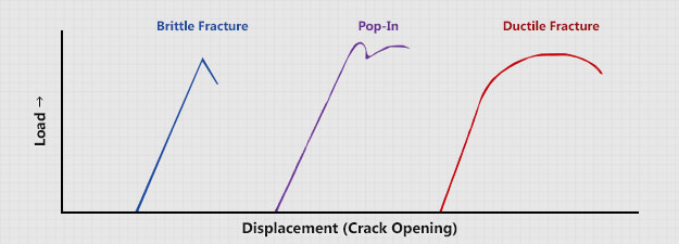
The crack tip opening is plotted against the load applied. There are three basic types of fracture behavior with this test: brittle fracture, pop-in, and ductile. The first curve shows a brittle fracture with little or no plastic deformation. The curve shows a pop-in where the crack initiates in a brittle manner but is soon arrested by tougher more ductile material. This behavior can occur many times giving the curve a saw tooth appearance. And the third curve depicts a completely plastic or ductile behavior.
Locating the notch correctly in the material being tested is important. A fatigue crack positioned incorrectly will not sample the required area thus invalidating the test.
Polishing, etching and metallurgical examination are often used to provide the required accuracy in notch placement. These techniques may also be employed after the test to provide additional confirmation of the validity of the test.
A low stress range is common when performing the fatigue cracking. Employing high stresses to speed up the process can cause large area of plastically deformed material to form ahead of the fatigue crack invalidating the test.
Examination of the fatigue crack surface is necessary to determine the success or failure of the test. The length of the crack itself is accurately measured. If the length of the crack is not within the specified limits the test is invalid. If the crack is not in a single plane, or at an angle to the machined notch, or, if the crack is not in the proper region, the test is invalid.
Continue Reading
Fracture Toughness Testing
Fracture Toughness »Fatigue Testing »
Low Cycle Fatigue »
Fastener Testing »
CTOD Testing »
Da/DN »
JIC »
KIC »