This test method covers the determination of the plane-strain fracture toughness (KIc) of metallic materials by increasing-force tests of fatigue pre-cracked specimens. Force is applied either in tension or three-point bending. Force versus crack-mouth opening displacement (CMOD) is recorded either autographically or digitally. The force at a 5 % secant offset from the initial slope (corresponding to about 2.0 % apparent crack extension) is established by a specified deviation from the linear portion of the record. The value of KIc is calculated from this force using equations that have been established by elastic stress analysis of the specimen configurations specified in this test method. The validity of the KIc value determined by this test method depends upon the establishment of a sharp-crack condition at the tip of the fatigue crack in a specimen having a size adequate to ensure predominantly linear-elastic, plane-strain conditions. To establish the suitable crack-tip condition, the stress-intensity factor level at which specimen fatigue pre-cracking is conducted is limited to a relatively low value. For complete information on ASTM E399, go to www.astm.org
221 Westmoreland Drive Latrobe, PA 15650 USA
P.O. Box 388 Youngstown, PA 15696-0388 USA
Fracture Toughness Testing

Westmoreland Mechanical Testing & Research has a world-renowned reputation for dependable Fracture Toughness Testing. Our state-of-the-art Fracture Lab is designed for the high volume, quick turnaround projects demanded by the aerospace, automotive, power generation, and medical industries.”
Expedited Fracture Toughness Testing Services Are Available- Contact Us Today at 724-537-3131
- Nadcap Accredited since 1992
- A2LA ISO 17025 621.01, 621.02 Accredited
- Capability to handle specimens of many sizes
- Testing can be performed on samples ranging from 0.25” up to 4.25” thickness
- Fracture Toughness can be performed at various load capacities up to 1,000,000 lbs.
- Testing can be performed at temperatures ranging from Liquid Helium to over 2400°F in both controlled and simulated atmospheres. Examples of atmospheres include salt water, argon, vacuum and high humidity
- Over 260 servo-hydraulic machines equipped to perform pre-cracking
- On-site machining and specimen preparation
- Customize test setups and fixtures
- Electronic Data Interface System (EDI) can transfer information directly and securely to your database
Westmoreland Mechanical Testing & Research is world renowned for superior work in the Fracture Mechanics field. Our top of the line Fracture Lab is designed to accommodate traditional Fracture Toughness testing, as well as specialty projects and unconventional specifications. Our ability to tackle increasing work-loads and to produce results quickly makes us a leader in Fracture Toughness Testing.

The most popular test performed in the Fracture Lab is the KIC Test per ASTM E399. Disc Shape, Arc Tension, Single Edge Bend and Compact Tension are all covered under the ASTM E399 specification. Our lab has the capability to handle specimens of many sizes. For example, the Compact Tension Test can be performed on samples ranging from 0.25” to 4.25” thick for most applications.
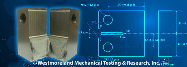
Pre-cracking is an essential part of Fracture Toughness testing. The pre-crack is the creation of a simulated “flaw” that aids in the testing of fractured specimens. The actual crack, which initiates at the tip of a machined notch, is typically measured automatically using compliance techniques. WMT&R can also perform pre-cracking.
Fracture Toughness tests can be performed at various load capacities and temperatures.
Our servo machines can cover up to a 1,000,000 lbs. load. WMT&R can also perform tests at temperatures ranging from Liquid Helium to cover 2400°F in both controlled and simulated atmospheres.
The K-R Curve testing per ASTM E561 can be performed on both compact specimens C(T) and center crack tension panels M(T). We have the unique ability to test large M(T) panels up to 30.0” wide.
The K-R curve test provides valuable data about the toughness development as a crack is progressively propagated under an increasing applied stress intensity factor K. R-Curves and applied K-Curves are used to predict the critical stress intensity that will cause the onset of unstable fracturing.
![]()
Chevron Notch Short Rod and Short Bar testing per ASTM E1304 can be performed in the Fracture Mechanics Lab. Through machining and testing experience, our facility is equipped to handle B dimensions ranging from 0.25” to 2.0”. The fracture toughness determined by this test shows the resistance of a material to fracture from a gradually advancing steady state crack utilizing a severe tensile constraint in a neutral environment. A KIV, KIVJ, or KIVM value may be assigned to estimate the correlation of failure and defect size.
Surface Crack Tension (SCT) testing, conducted to ASTM E740, estimates the load carrying capacity of sheet or plate components when a flaw has occurred. It is not uncommon for our Fracture Department to perform this test to cryogenic temperatures as low as -423ºF. The purpose of this test is to study the failure characteristics of cracks under simulated service conditions.
Additional Fracture Mechanics Testing Services:
- KIC
- Chevron Notch
- Short Rod
- Short Bar
- R-Curve Determinations
- Drop-Weight Tear Tests
- Nil Ductility Transition Temperature
- JIC
- CTOD
- Dynamic Tear Testing
- Notched Bar Impact (Charpy and Izod)
Westmoreland Mechanical Testing & Research can provide the following Fracture Mechanics standard tests:
ASTM E399
ASTM E1820
ASTM E561
ASTM E740
ASTM E1304
ASTM E1681
ASTM E1820
ASTM E1921
ASTM E208
ASTM E604
The information on the following ASTM standard tests are provided “as is” without warranty of any kind. WMT&R does not accept any responsibility or liability for the accuracy, content, completeness or the reliability of the information mentioned under each test. The information is partial and is taken from the current ASTM test listing at the time of publication. For complete and current test specifications and detail go to www.astm.org.
ASTM E399
Standard Test Method for Linear-Elastic Plane-Strain Fracture Toughness K1C of Metallic Materials
This test method covers the determination of fracture toughness (KIc) of metallic materials under predominantly linear-elastic, plane-strain conditions using fatigue pre-cracked specimens having a thickness of 1.6 mm (0.063 in.) or greater subjected to slowly, or in special (elective) cases rapidly, increasing crack-displacement force.

ASTM E1820
Standard Test Method for Measurement of Fracture Toughness
This test method covers procedures and guidelines for the determination of fracture toughness of metallic materials using the following parameters: K, J, and CTOD (δ). Toughness can be measured in the R-curve format or as a point value. The fracture toughness determined in accordance with this test method is for the opening mode (Mode I) of loading.
The objective of this test method is to load a fatigue pre-cracked test specimen to induce either or both of the following responses (1) unstable crack extension, including significant pop-in, referred to as "fracture instability" in this test method; (2) stable crack extension, referred to as "stable tearing" in this test method. Fracture instability results in a single point-value of fracture toughness determined at the point of instability. Stable tearing results in a continuous fracture toughness versus crack-extension relationship (R-curve) from which significant point-values may be determined. Stable tearing interrupted by fracture instability results in an R-curve up to the point of instability.
This test method requires continuous measurement of force versus load-line displacement or crack mouth opening displacement, or both. If any stable tearing response occurs, then an R-curve is developed and the amount of slow-stable crack extension shall be measured.
Assuming the presence of a preexisting, sharp, fatigue crack, the material fracture toughness values identified by this test method characterize its resistance to: (1) fracture of a stationary crack, (2) fracture after some stable tearing, (3) stable tearing onset, and (4) sustained stable tearing. This test method is particularly useful when the material response cannot be anticipated before the test.
For complete information on ASTM E1820, go to www.astm.org
ASTM E561
Standard Test Method for K-R Curve Determination
This test method covers the determination of the resistance to fracture of metallic materials under Mode I loading at static rates using either of the following notched and pre-cracked specimens: the middle-cracked tension M(T) specimen or the compact tension C(T) specimen. A KR curve is a continuous record of toughness development (resistance to crack extension) in terms of KR plotted against crack extension in the specimen as a crack is driven under an increasing stress intensity factor, K.
Materials that can be tested for KR curve development are not limited by strength, thickness, or toughness, so long as specimens are of sufficient size to remain predominantly elastic to the effective crack extension value of interest. Specimens of standard proportions are required, but size is variable, to be adjusted for yield strength and toughness of the materials. Only two of the many possible specimen types that could be used to develop KR curves are covered in this method. The test is applicable to conditions where a material exhibits slow, stable crack extension under increasing crack driving force, which may exist in relatively tough materials under plane stress crack tip conditions. The values stated in SI units are to be regarded as the standard. The values given in parentheses are for information only.
The KR curve characterizes the resistance to fracture of materials during slow, stable crack extension and results from the growth of the plastic zone ahead of the crack as it extends from a fatigue pre-crack or sharp notch. It provides a record of the toughness development as a crack is driven stably under increasing applied stress intensity factor K. For a given material, KRcurves are dependent upon specimen thickness, temperature, and strain rate. The amount of valid KR data generated in the test depends on the specimen type, size, method of loading, and, to a lesser extent, testing machine characteristics. For an untested geometry, the KR curve can be matched with the crack driving (applied K) curves to estimate the degree of stable crack extension and the conditions necessary to cause unstable crack propagation In making this estimate, KRcurves are regarded as being independent of original crack size ao and the specimen configuration in which they are developed. For a given material, material thickness, and test temperature, KRcurves appear to be a function of only the effective crack extension Δae. To predict crack behavior and instability in a component, a family of crack driving curves is generated by calculating K as a function of crack size for the component using a series of force, displacement, or combined loading conditions. The KRcurve may be superimposed on the family of crack driving curves with the origin of the KR curve coinciding with the assumed original crack size ao. The intersection of the crack driving curves with the KR curve shows the expected effective stable crack extension for each loading condition. The crack driving curve that develops tangency with the KR curve defines the critical loading condition that will cause the onset of unstable fracture under the loading conditions used to develop the crack driving curves. For complete information on ASTM E561, go to www.astm.org
ASTM E740
Standard Practice for Fracture Testing with Surface Crack Tension Specimens
This practice covers the design, preparation, and testing of surface-crack tension (SCT) specimens. It relates specifically to testing under continuously increasing force and excludes cyclic and sustained loadings. The quantity determined is the residual strength of a specimen having a semielliptical or circular-segment fatigue crack in one surface. This value depends on the crack dimensions and the specimen thickness as well as the characteristics of the material.
Metallic materials that can be tested are not limited by strength, thickness, or toughness. However, tests of thick specimens of tough materials may require a tension test machine of extremely high capacity. The applicability of this practice to nonmetallic materials has not been determined.
This practice is limited to specimens having a uniform rectangular cross section in the test section. The test section width and length must be large with respect to the crack length. Crack depth and length should be chosen to suit the ultimate purpose of the test.
Residual strength may depend strongly upon temperature within a certain range depending upon the characteristics of the material. This practice is suitable for tests at any appropriate temperature.
Residual strength is believed to be relatively insensitive to loading rate within the range normally used in conventional tension tests. When very low or very high rates of loading are expected in service, the effect of loading rate should be investigated using special procedures that are beyond the scope of this practice.
The surface-crack tension (SCT) test is used to estimate the load-carrying capacity of simple sheet- or plate-like structural components having a type of flaw likely to occur in service. The test is also used for research purposes to investigate failure mechanisms of cracks under service conditions.
The residual strength of an SCT specimen is a function of the crack depth and length and the specimen thickness as well as the characteristics of the material. This relationship is extremely complex and cannot be completely described or characterized at present.
The results of the SCT test are suitable for direct application to design only when the service conditions exactly parallel the test conditions.
In order that SCT test data can be comparable and reproducible and can be correlated among laboratories, it is essential that uniform SCT testing practices be established.
The specimen configuration, preparation, and instrumentation described in this practice are generally suitable for cyclic- or sustained-force testing as well. However, certain constraints are peculiar to each of these tests. For complete information on ASTM E740, go to www.astm.org
ASTM E1304
Standard Test Method Plane-Strain (Chevron-Notch) Fracture Toughness of Metallic Materials
This test method covers the determination of plane-strain (chevron-notch) fracture toughnesses, KIv or KIvM, of metallic materials. Fracture toughness by this method is relative to a slowly advancing steady state crack initiated at a chevron-shaped notch, and propagating in a chevron-shaped ligament. Some metallic materials, when tested by this method, exhibit a sporadic crack growth in which the crack front remains nearly stationary until a critical load is reached. The crack then becomes unstable and suddenly advances at high speed to the next arrest point. For these materials, this test method covers the determination of the plane-strain fracture toughness, KIvj or KIvM, relative to the crack at the points of instability.
The fracture toughness determined by this test method characterizes the resistance of a material to fracture by a slowly advancing steady-state crack in a neutral environment under severe tensile constraint. The state of stress near the crack front approaches plane strain, and the crack-tip plastic region is small compared with the crack size and specimen dimensions in the constraint direction. A KIv or KIvj value may be used to estimate the relation between failure stress and defect size when the conditions described above would be expected, although the relationship may differ from that obtained from a KIc value.
The KIv, KIvj, or KIvM value of a given material can be a function of testing speed (strain rate) and temperature. Furthermore, cyclic forces can cause crack extension at KI values less than KIv, and crack extension can be increased by the presence of an aggressive environment. Therefore, application of KIv in the design of service components should be made with an awareness of differences that may exist between the laboratory tests and field conditions.
Plane-strain fracture toughness testing is unusual in that there can be no advance assurance that a valid KIv, KIvj, or KIvMwill be determined in a particular test. Therefore, it is essential that all the criteria concerning the validity of results be carefully considered as described herein. This test method can serve the following purposes: To establish the effects of metallurgical variables such as composition or heat treatment, or of fabricating operations such as welding or forming, on the fracture toughness of new or existing materials.
For specifications of acceptance and manufacturing quality control, but only when there is a sound basis for specification of minimum KIv, KIvj, or KIvM values, and then only if the dimensions of the product are sufficient to provide specimens of the size required for valid KIv determination. The specification of KIv values in relation to a particular application should signify that a fracture control study has been conducted on the component in relation to the expected history of loading and environment, and in relation to the sensitivity and reliability of the crack detection procedures that are to be applied prior to service and subsequently during the anticipated life. To provide high spatial resolution in measuring plane strain fracture toughness variations in parent pieces of material.
NOTE 2: The high spatial resolution is possible because of the small allowable specimen size criterion, B ≥1.25 (KIv /σYS)2, and because the toughness is measured at approximately the midline of the specimen, and only in the material covered by the crack's lateral extent, which is about one third of the specimen's lateral dimension, B. For complete information on ASTM E1304, go to www.astm.org
ASTM E1681
Standard Test Method for Determining Threshold Stress Intensity Factor for Environment Assisted Cracking of Metallic Materials
This test method covers the determination of the environment-assisted cracking threshold stress intensity factor parameters, KIEAC and KEAC, for metallic materials from constant-force testing of fatigue pre-cracked beam or compact fracture specimens and from constant-displacement testing of fatigue pre-cracked bolt-load compact fracture specimens.
This test method is applicable to environment-assisted cracking in aqueous or other aggressive environments.
Materials that can be tested by this test method are not limited by thickness or by strength as long as specimens are of sufficient thickness and planar size to meet the size requirements of this test method.
A range of specimen sizes with proportional planar dimensions is provided, but size may be variable and adjusted for yield strength and applied force. Specimen thickness is a variable independent of planar size.
Specimen configurations other than those contained in this test method may be used, provided that well-established stress intensity calibrations are available and that specimen dimensions are of sufficient size to meet the size requirements of this test method during testing.
The parameters KEAC or KIEAC determined by this test method characterize the resistance to crack growth of a material with a sharp crack in specific environments under loading conditions in which the crack-tip plastic region is small compared with the crack depth and the uncracked ligament. The less restrictive thickness requirements of KEAC are intended for those conditions in which the results are a strong function of the thickness of the specimen and the application requires the testing of specimens with thickness representative of the application. Since the chemical and mechanical influences cannot be separated, in some material/environment combinations, the thickness must be treated as a variable. A KEAC or KIEAC value is believed to represent a characteristic measurement of environment-assisted cracking resistance in a pre-cracked specimen exposed to an environment under sustained tensile loading. A KEAC or KIEAC value may be used to estimate the relationship between failure stress and defect size for a material under any service condition, where the combination of crack-like defects, sustained tensile loading and the same specific environment would be expected to occur.
The apparent KEAC or KIEAC of a material under a given set of chemical and electrochemical environmental conditions is a function of the test duration. It is difficult to furnish a rigorous and scientific proof for the existence of a threshold. Therefore, application of KEAC or KIEAC data in the design of service components should be made with awareness of the uncertainty inherent in the concept of a true threshold for environment-assisted cracking in metallic materials. A measured KEAC or KIEAC value for a particular combination of material and environment may, in fact, represent an acceptably low rate of crack growth rather than an absolute upper limit for crack stability. Care should be exercised when service times are substantially longer than test times.
The degree to which force deviations from static tensile stress will influence the apparent KEAC or KIEAC of a material is largely unknown. Small-amplitude cyclic loading, well below that needed to produce fatigue crack growth, superimposed on sustained tensile loading was observed to significantly lower the apparent threshold for stress corrosion cracking in certain instances. Therefore, caution should be used in applying KEAC or KIEAC data to service situations involving cyclic loading. In addition, since this standard is for static loading, small-amplitude cyclic loading should be avoided during testing.
In some material/environment combinations, the smaller the specimen, the lower the measured KEAC value, while in other material/environment combinations the measured KIEAC value will be the lowest value. If, for the material/environment combination of interest, it is not known which specimen size will result in the lower measured value, then it is suggested that the use of both specimen sizes should be considered; that is, specimens with thicknesses representative of the application and specimens in which the thickness meets the requirements of a KIEAC value. The user may optionally determine and report a KEAC value or a KIEAC value. The specimen size validity requirements for a KEAC value meet the size requirements developed for Test Method E647 to achieve predominately elastic behavior in the specimen. Test Method E647 size requirements for compact specimens should be applied to both the compact specimen and the beam specimen. The specimen size validity requirements for a KIEAC value meet the size requirements developed for plane strain conditions for Test Method E399.
Evidence of environment-assisted crack growth under conditions that do not meet the validity requirements of may provide an important indication of susceptibility to environmental cracking but cannot be used to determine a valid KEAC value. Environment-assisted cracking is influenced by both mechanical and electrochemical driving forces. The latter can vary with crack depth, opening, or shape and may not be uniquely described by the fracture mechanics stress intensity factor. As an illustrative example, note the strong decrease reported in KISCC with decreasing crack size below 5 mm for steels in 3 % NaCl in water solution. Geometry effects on K similitude should be experimentally assessed for specific material/environment systems. Application modeling based on KEAC similitude should be conducted with caution when substantial differences in crack and specimen geometry exist between the specimen and the component. Not all combinations of material and environment will result in environment-assisted cracking. In general, susceptibility to aqueous stress-corrosion cracking decreases with decreasing material strength level. When a material in a certain environment is not susceptible to environment-assisted cracking, it will not be possible to measure KEAC or KIEAC. This method can serve the following purposes:
In research and development, valid KEAC or KIEAC data can quantitatively establish the effects of metallurgical and environmental variables on the environment-assisted cracking resistance of materials.
In service evaluation, valid KEAC or KIEAC data can be utilized to establish the suitability of a material for an application with specific stress, flaw size, and environmental conditions. In acceptance and quality control specifications, valid KEAC or KIEAC data can be used to establish criteria for material processing and component inspection.
Test results will be affected by force relaxation in constant displacement bolt-loaded compact specimens for some material/environment conditions. For relatively low strength material, non-aggressive environments, or high test temperatures, force relaxation can occur independently from environment-assisted cracking. Significant force relaxation would make cracking results difficult to interpret. If force relaxation is suspected of influencing the data, the following trial specimen test is recommended. Test a trial specimen with all the test conditions of interest, except with no environment applied. Monitor the force on the sample using a bolt with an electronic load cell attached. Instrumented bolts of this type are commercially available. A force relaxation of more than 5 % after 24 h indicates that the constant displacement test method may not be suitable for these test conditions, and a constant force test should be considered.
Residual stresses can have an influence on environment-assisted cracking. The effect can be significant when test specimens are removed from material in which complete stress relief is impractical, such as weldments, as-heat-treated materials, complex wrought parts, and parts with intentionally produced residual stresses. Residual stresses superimposed on the applied stress can cause the local crack-tip stress-intensity factor to be different from that calculated from externally applied forces or displacements. Irregular crack growth during pre-cracking, such as excessive crack front curvature or out-of-plane crack growth, often indicates that residual stresses will affect the subsequent environment-assisted crack growth behavior. Changes in the zero-force value of crack-mouth-opening displacement as a result of pre-crack growth is another indication that residual stresses will affect the subsequent environment-assisted crack growth.
For bolt loaded specimens, the user should realize that material being tested at an non-ambient temperature may have a different displacement-to-force ratio from that at ambient temperature, and also the bolt material may have a different coefficient of thermal expansion from that of the material being tested. Care should be taken to minimize these effects. For complete information on ASTM E1681, go to www.astm.org
ASTM E1820
Standard Test Method for Measurement of Fracture Toughness
This test method covers procedures and guidelines for the determination of fracture toughness of metallic materials using the following parameters: K, J, and CTOD (δ). Toughness can be measured in the R-curve format or as a point value. The fracture toughness determined in accordance with this test method is for the opening mode (Mode I) of loading.
NOTE 1: Until this version, KIc could be evaluated using this test method as well as by using Test Method E399. To avoid duplication, the evaluation of KIc has been removed from this test method and the user is referred to Test Method E399. The recommended specimens are single-edge bend, [SE(B)], compact, [C(T)], and disk-shaped compact, [DC(T)]. All specimens contain notches that are sharpened with fatigue cracks.
Specimen dimensional (size) requirements vary according to the fracture toughness analysis applied. The guidelines are established through consideration of material toughness, material flow strength, and the individual qualification requirements of the toughness value per values sought.
Other standard methods for the determination of fracture toughness using the parameters K, J, and CTOD are contained in Test Methods E399, E1290, and E1921. This test method was developed to provide a common method for determining all applicable toughness parameters from a single test. For complete information on ASTM E1820, go to www.astm.org
ASTM E1921
Standard Test Method for Determination of Reference Temperature, T, for Ferritic Steels in the Transition Range
This test method covers the determination of a reference temperature, To, which characterizes the fracture toughness of ferritic steels that experience onset of cleavage cracking at elastic, or elastic-plastic KJc instabilities, or both. The specific types of ferritic steels covered are those with yield strengths ranging from 275 to 825 MPa (40 to 120 ksi) and weld metals, after stress-relief annealing, that have 10 % or less strength mismatch relative to that of the base metal.
The specimens covered are fatigue pre-cracked single-edge notched bend bars, SE(B), and standard or disk-shaped compact tension specimens, C(T) or DC(T). A range of specimen sizes with proportional dimensions is recommended. The dimension on which the proportionality is based is specimen thickness. Median KJc values tend to vary with the specimen type at a given test temperature, presumably due to constraint differences among the allowable test specimens in. The degree of KJc variability among specimen types is analytically predicted to be a function of the material flow properties and decreases with increasing strain hardening capacity for a given yield strength material. This KJc dependency ultimately leads to discrepancies in calculated To values as a function of specimen type for the same material. To values obtained from C(T) specimens are expected to be higher than To values obtained from SE(B) specimens. Best estimate comparisons of several materials indicate that the average difference between C(T) and SE(B)-derived To values is approximately 10°C. C(T) and SE(B) To differences up to 15°C have also been recorded. However, comparisons of individual, small datasets may not necessarily reveal this average trend. Datasets which contain both C(T) and SE(B) specimens may generate To results which fall between the To values calculated using solely C(T) or SE(B) specimens. It is therefore strongly recommended that the specimen type be reported along with the derived To value in all reporting, analysis, and discussion of results.
Requirements are set on specimen size and the number of replicate tests that are needed to establish acceptable characterization of KJc data populations.
The statistical effects of specimen size on KJc in the transition range are treated using the weakest-link theory applied to a three-parameter Weibull distribution of fracture toughness values. A limit on KJc values, relative to the specimen size, is specified to ensure high constraint conditions along the crack front at fracture. For some materials, particularly those with low strain hardening, this limit may not be sufficient to ensure that a single-parameter (KJc) adequately describes the crack-front deformation state.
Statistical methods are employed to predict the transition toughness curve and specified tolerance bounds for 1T specimens of the material tested. The standard deviation of the data distribution is a function of Weibull slope and median KJc. The procedure for applying this information to the establishment of transition temperature shift determinations and the establishment of tolerance limits is prescribed.
This test method assumes that the test material is macroscopically homogeneous such that the materials have uniform tensile and toughness properties. The fracture toughness evaluation of non-uniform materials is not amenable to the statistical analysis methods employed in the main body of this test method. Application of the analysis of this test method to an inhomogeneous material will result in an inaccurate estimate of the transition reference value To and non-conservative confidence bounds. For example, multi-pass weldments can create heat-affected and brittle zones with localized properties that are quite different from either the bulk material or weld. Thick section steels also often exhibit some variation in properties near the surfaces. Metallography and initial screening may be necessary to verify the applicability of these and similarly graded materials. For complete information on ASTM E1921, go to www.astm.org
Standard Test Method for Conducting Drop-Weight test to Determine Nil-Ductility Transition Temperature of Ferritic Steels
The ASTM E208 Drop-Weight Test is used primarily to determine the Nil-ductility transition temperature or NDT of ferritic steels of 5/8 in thickness and over. This particular drop weight test was initially developed by the Naval Research Laboratory in 1952 and published as Department of the Navy document NAVSHIPS-250-634-3.
Nil-ductility transition temperature is the temperature at which the fracture mode of the steel changes from ductile to brittle. Above the NDT a piece of steel typically will stretch or deform 20% - 40% before fracture when loaded to its ultimate tensile strength. However, below the NDT the same piece of steel will fracture in a brittle manner like glass when only loaded to yield strength (about half of the ultimate strength). Once it begins to crack in this manner the crack will continue to propagate at the speed of sound. It will only stop when it runs out of steel, the load is released, or until the crack is interrupted by steel that is behaving in a ductile manner due to different qualities in the steel or different temperatures present.
The drop-weight test consists of beam specimens prepared according to ASTM E208 specifications to initiate a material crack in a selected area of their tensile surfaces at the start of the test. During the test a series of specimens is subjected to a single impact load at a progression of selected temperatures to determine the maximum temperature at which a specimen breaks. The impact load is delivered by a guided, free-falling weight with an energy of 250 to 1200 ft-lb (340 to 1630 J) according to the yield strength of the steel to be tested. A stop is employed to prevent deflection of more than a few tenths of an inch.
After the specimen is prepared properly for the crack initiation, and conditioned to the proper temperature, the test begins. The initial test is conducted at a temperature estimated to be near the NDT temperature. The remaining specimens are then tested at a progression of temperature intervals to determine the break and no-break performance temperatures within 10°F or (5°C). For complete information on ASTM E208, go to www.astm.org
ASTM E604
Standard Test Method for Dynamic Tear Testing of Metallic Materials
This test method covers the dynamic tear (DT) test using specimens that are 3/16 in. to 5/8 in. (5 mm to 16 mm) inclusive in thickness.
This test method is applicable to materials with a minimum thickness of 3/16 in. (5 mm).
The pressed-knife procedure described for sharpening the notch tip generally limits this test method to materials with a hardness level less than 36 HRC.
The designation 36 HRC is a Rockwell hardness number of 36 on Rockwell C scale as defined in Test Methods.
The values stated in inch-pound units are to be regarded as standard. The values given in parentheses are mathematical conversions to SI units that are provided for information only and are not considered standard.
The DT energy value is a measure of resistance to rapid progressive fracturing. In a number of applications, the enhanced resistance that may develop during about one plate thickness of crack extension from a sharp notch is of major interest. In the test method, a sufficiently long fracture path is provided so that the results serve as a measure of this property. Fracture surfaces of non-austenitic steels tested in their temperature transition region have areas that appear bright and areas that appear dull. The bright, faceted appearing areas are termed "cleavage" fracture, and the dull appearing areas are termed "shear" fracture after their respective mode of fracture on a micro scale.
This test method can serve the following purposes: In research and development, to evaluate the effects of metallurgical variables such as composition, processing, or heat treatment, or of fabricating operations such as forming and welding on the dynamic tear fracture resistance of new or existing materials.
In service evaluation, to establish the suitability of a material for a specific application only where a correlation between DT energy and service performance has been established.3 For information, specifications of acceptance, and manufacturing quality control when a minimum DT energy is requested. Detailed discussion of the basis for determining such minimum values in a particular case is beyond the scope of this test method. For complete information on ASTM E604, go to www.astm.org
Heat Treatment Capabilities
Westmoreland Mechanical Testing & Research maintains capabilities to heat treat material to various conditions onsite. Our facilities can handle a wide variety of thermo-mechanical processing.
For ferrous alloys:
- Radiant Furnaces and Environmental Chambers
- Homogenizing, Annealing, Spheroidizing, Process/Recrystallization Annealing, Stress Relieving
- Normalizing, Quenching, and Tempering up to +2750°F
- Cryogenic treatments down to -320°F
For non-ferrous alloys:
- Forced Convection Furnaces
- Solution Treating, Annealing, and Artificial Aging up to +1200°F
Manufacturing Technologies
On-Site Mechanical Engineering
The on-site Mechanical Engineering laboratory is staffed by specialists and engineers in product evaluation of actual prototype components and subassemblies. From custom design and fabrication of fixtures, to conducting the test, our mechanical engineers have the expertise and resources to assist our various testing departments in delivering data to customers in an efficient and timely manner.
On-Site Machine Shop
The on-site high-technology, full-service Machine Shop at Westmoreland Mechanical Testing & Research encompasses a clean, temperature-controlled environment and state-of-the-art equipment, with the ability to machine all test specimens onsite. In addition to machining standard specimens, our Machine Shop has the ability and resource to custom-design and machine fixtures for testing finished parts, odd shapes, and difficult or exotic materials.
Our reputation for quality machining and superior turnaround times brings us production work from other laboratories and mills. With our advanced in-house capabilities, and substantial engineering experience, we are known as specialists in low-stress grinding and machining sub size specimens to very close tolerances.
Continue Reading
Fracture Toughness Testing
Fracture Toughness »Fatigue Testing »
CTOD Testing »
Da/DN »
JIC »
KIC »